
The RP2040 Zero pinout diagram shows all GPIO pins, power pins and communication interfaces. This guide helps you understand how to safely connect sensors, displays and external modules.
RP2040 Zero Pinout Diagram
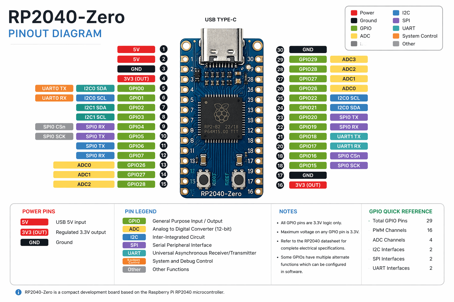
The RP2040 Zero GPIO layout includes digital pins, power pins and communication interfaces such as SPI, I2C and UART. Always verify pin connections before powering your circuit.
RP2040 Zero GPIO Explained
Power Pins
GND – ground
5V – USB power input
3.3V – regulated output
RP2040 Zero Board Overview
RP2040 Zero is a compact development board based on the RP2040 microcontroller.
Its small size and flexible GPIO configuration make it ideal for embedded projects, DIY electronics and IoT applications.
GPIO Pins
RP2040 Zero has multiple GPIO pins that can be configured as input or output. These pins support PWM, digital signals and communication protocols.
Communication Interfaces
UART – for serial communication
I2C – for sensors and displays
SPI – for fast communication devices
RP2040 Zero Pin Functions
RP2040 GPIO pins can be configured for multiple functions depending on the software. This flexibility allows you to use the same pin for different tasks such as PWM output, analog reading or communication.
Important Notes
Double-check wiring before powering
All GPIO pins use 3.3V logic
Do not connect 5V directly to GPIO
Use common ground for all modules
Related Guides
🔊 PCM5102A DAC Guide
I2S audio decoder module for Raspberry Pi.
📶 ESP32 Mini Guide
Ultra-compact ESP32 board with WiFi.
📡 ESP32 LoRa SX1276 Guide
ESP32 board with LoRa and OLED display.
Explore More Guides
Looking for more tutorials and microcontroller guides? Explore our full collection to find the right module for your project.