
The PCM5102A pinout diagram shows all power pins, I2S interface pins and audio output connections.
This guide helps you correctly connect the module to microcontrollers and audio systems.
PCM5102A Pinout Diagram
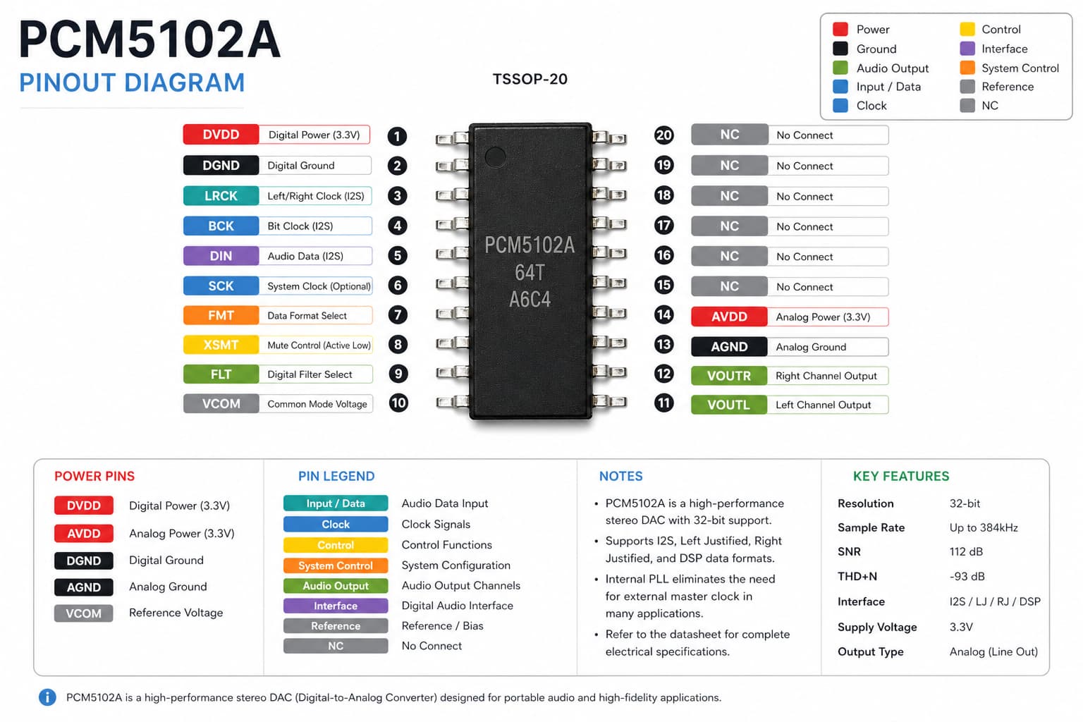
The PCM5102A pinout includes I2S signal pins, power connections and audio output lines. Proper wiring ensures clean and stable sound output.
PCM5102A Pin Functions
Power Pins
- VCC – power supply
- GND – ground
I2S Interface Pins
- BCK – bit clock
- LRCK – left/right channel clock
- DIN – digital audio input
Audio Output
- LOUT – left channel output
- ROUT – right channel output
PCM5102A Wiring with ESP32
Typical connection:
- BCK → GPIO (ESP32)
- LRCK → GPIO
- DIN → GPIO
- VCC → 3.3V or 5V
- GND → GND
PCM5102A Wiring with Raspberry Pi
PCM5102A works perfectly with Raspberry Pi using the I2S interface.
You can use it to build high-quality audio players and media systems.
Important Notes
- Use stable power supply
- Keep wires short to reduce noise
- Ensure correct I2S pin mapping
- Avoid incorrect voltage connections
PCM5102A Audio Overview
PCM5102A provides high-quality digital-to-analog conversion with low noise and distortion.
It is widely used in DIY audio projects and embedded sound systems.
Related Guides
🔌 RP2040 Zero Guides
Pinout, Arduino setup and projects
📡 NRF52840 Guide
Wireless setup and communication
🌐 WT32-ETH01 Guide
Ethernet ESP32 setup and usage
Explore More Guides
Looking for more electronics tutorials? Explore our guides and find the best components for your project.