
The ESP32 Mini pinout diagram shows all GPIO pins, power pins and communication interfaces of the board.
This guide helps you understand how to connect sensors, modules and external devices correctly.
ESP32 Mini Pinout Diagram
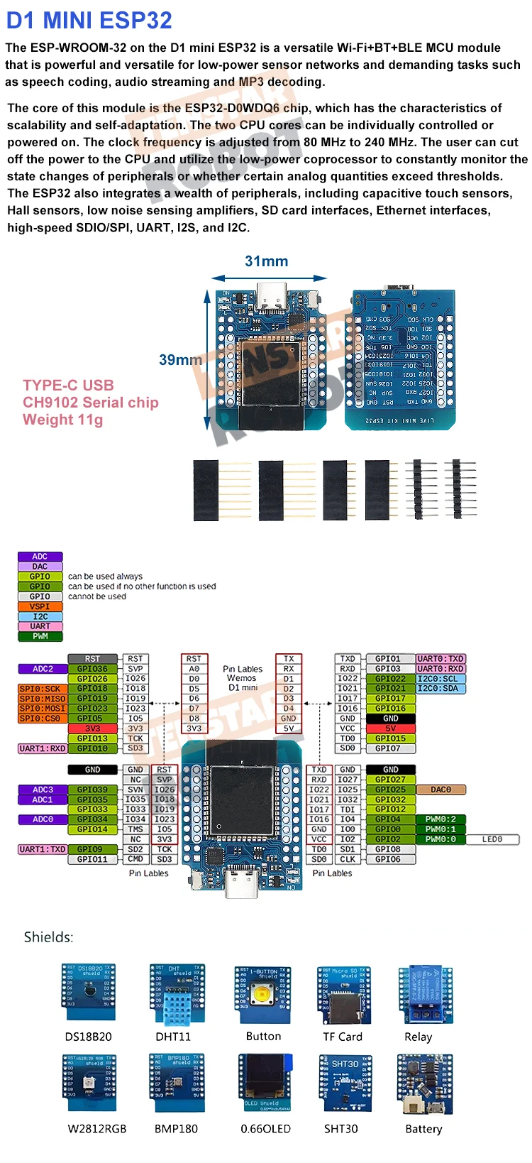
This ESP32 Mini pinout diagram shows all GPIO pins, power pins and communication interfaces including SPI, I2C and UART.
Understanding the ESP32 GPIO layout helps you safely connect modules and avoid wiring mistakes.
ESP32 Mini GPIO Explained
Power Pins
- 3.3V – power output
- 5V – USB power input
- GND – ground
GPIO Pins
ESP32 Mini provides multiple GPIO pins that can be configured as input or output.
They support PWM, digital signals and advanced features.
Communication Interfaces
- I2C – for sensors and displays
- SPI – for high-speed communication
- UART – for serial communication
ESP32 Mini GPIO Layout
ESP32 GPIO pins are flexible and can be assigned to different functions depending on the firmware.
Some pins are used during boot, so check pin usage before wiring.
Important Notes
- Use 3.3V logic for GPIO
- Do not connect 5V directly
- Avoid using boot pins incorrectly
- Ensure stable power supply
ESP32 Mini Board Overview
ESP32 Mini is a compact development board with WiFi and Bluetooth connectivity.
It is widely used in IoT projects, smart devices and automation systems.
Related Guides
🔌 RP2040 Zero Guides
Pinout, Arduino setup and projects
📡 NRF52840 Guide
Wireless setup and communication
🌐 WT32-ETH01 Guide
Ethernet ESP32 setup and usage
Explore More Guides
Looking for more electronics tutorials? Explore our guides and find the best components for your project.