
The ESP32 LoRa SX1276 pinout diagram shows GPIO pins, power pins and LoRa module connections.
This guide helps you correctly wire the board for long-range wireless communication.
ESP32 LoRa SX1276 Pinout Diagram
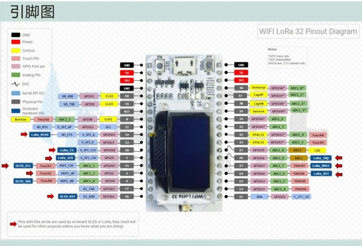
This ESP32 LoRa SX1276 pinout diagram shows GPIO pins, power pins and LoRa module connections including SPI communication.
Understanding the pin layout helps you correctly connect antennas and external modules.
ESP32 LoRa SX1276 GPIO Explained
Power Pins
- 5V – power input
- 3.3V – regulated output
- GND – ground
GPIO Pins
ESP32 provides flexible GPIO pins that can be used for input, output and communication.
Some pins are used internally by the LoRa module.
LoRa Module Connections (SX1276)
Typical connection uses SPI interface between ESP32 and SX1276 module.
Make sure SPI pins are correctly mapped and not conflicting with other peripherals.
Important Notes
- Use correct LoRa frequency (868MHz / 915MHz)
- Always connect antenna
- Use stable power supply
- Avoid incorrect GPIO usage
ESP32 LoRa Board Overview
ESP32 LoRa SX1276 combines WiFi, Bluetooth and long-range communication in one board.
It is widely used in remote monitoring, agriculture and IoT networks.
Related Guides
🔌 RP2040 Zero Guides
Pinout, Arduino setup and projects
📡 NRF52840 Guide
Wireless setup and communication
🌐 WT32-ETH01 Guide
Ethernet ESP32 setup and usage
Explore More Guides
Looking for more tutorials? Explore our guides to find the right board for your project.